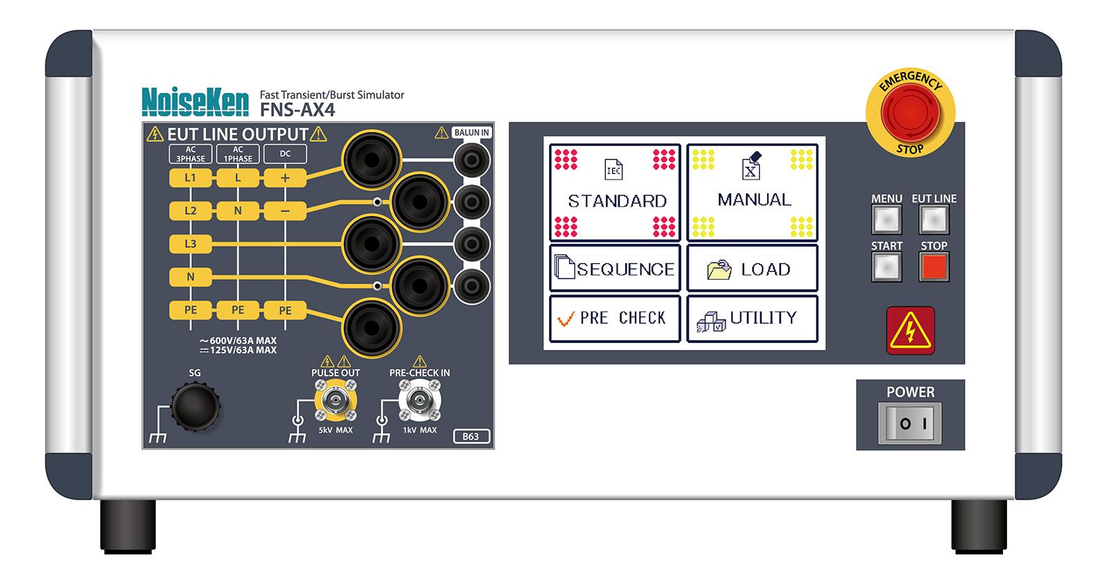
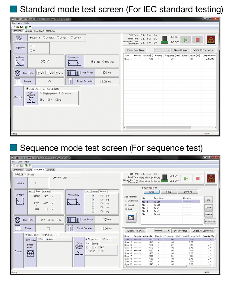
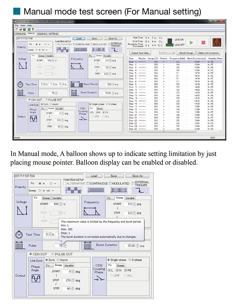
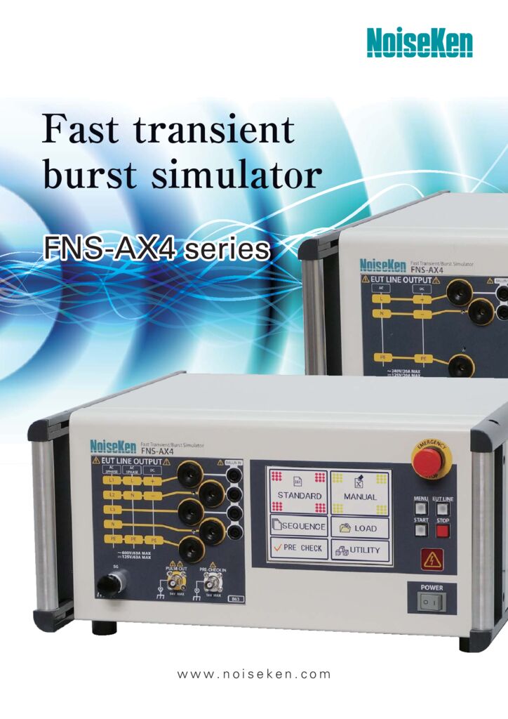
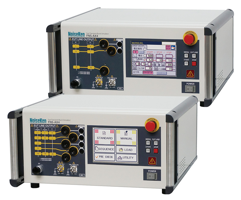
Fast Transient Burst Simulator(FNS) Fast transient / burst simulator FNS-AX4-A20 / B63
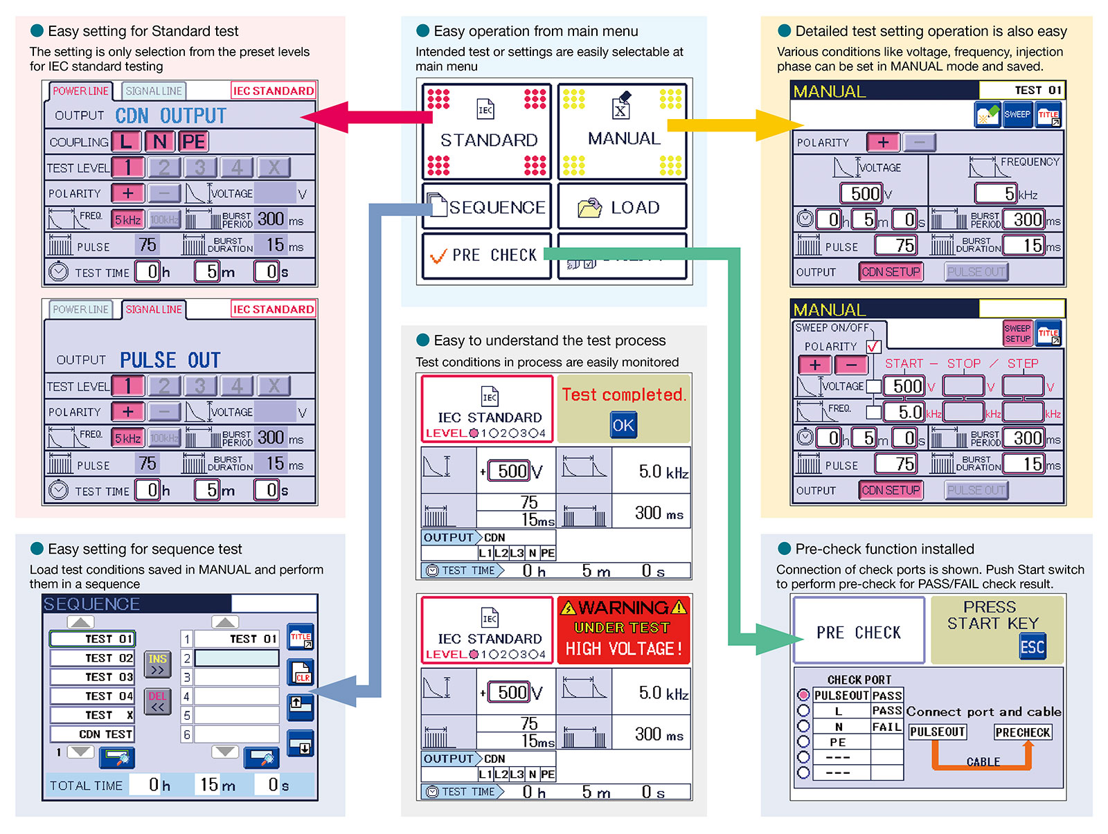
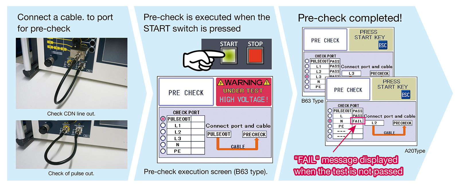
It is compact and equipped with new functions to make EMC testing easier.
It is a tester that evaluates the resistance of electronic devices by simulating high-frequency noise that rises quickly due to discharge between contacts of switching devices and arc discharge generated from electronic motors.
ポップアップタイトル
closeSpecifications
■ Generator specifications
| Parameter | Specification / Function |
|---|---|
| Output voltage | 200 to 5000 V 10 V Step |
| Polarity | Positive or negative, polarity alternation possible per burst |
| Repetition frequency | 0.1 kHz to 2000 kHz 0.1 kHz to 1 kHz / 0.01 kHz step Tolerance ± 5%, 1.0 kHz to 10 kHz / 0.1 kHz step Tolerance ± 5% 10 kHz to 100 kHz / 1 kHz step Tolerance ± 5%, 100 kHz to 1000 kHz / 10 kHz step Tolerance ± 5% 1000 kHz to 2000 kHz / 100 kHz step Tolerance ± 10%, (Limitation per voltage levels when continuous output) |
| Number of pulses | 1 to 1000 at a step of 1 pulse , Setting limit: 1 pulse per ms in a burst (repetition frequency 1 kHz or more) |
| Burst duration | Formula for Burst duration = Pulse number / Repetition Frequency Scope of manually setting value for burst duration: 0.01 to 999 ms |
| Burst period | 10 to 1000ms ± 10% 10ms steps (500ms or more for polarity alternate mode) |
| Polarity alternate function | Output polarity alternated between positive and negative at each burst period Setting condition: the burst period is 500ms or more and the burst pause period [ (burst period) - (burst duration)] is 100ms or more Maximum test time: 10 minutes |
| Continuous Pulse output | Up to 1000 V -10 kHz or less, to 2000 V -4 kHz or less, to 5000 V -1 kHz or less. Maximum test time for each case: 10 min |
| Frequency modulation | Frequency is shifted continuously between set frequency and approximately -10% from the set frequency. The modulating wave is triangular wave of approximately 20Hz |
| External trigger | External trigger input invokes 1 burst output in synchronization with the trigger input. Trigger specification: Hi (+ 5V) → Lo (0 V) triggers one burst period. |
| Pulse waveform (at 50 Ω load) | Pulse peak voltage: (set voltage / 2) ± 10% Rise time: 5 ns ± 30% Pulse width: 50 ns ± 30% |
| Pulse waveform (at 1 kΩ load) | Pulse peak voltage: (set voltage x 0.95) ± 20% Rise time: 5 ns ± 30% Pulse width: 35 to 150 ns |
| DC blocking capacitor | 10nF ± 20% |
■ CDN specifications
| Parameter | Specification / Function |
|---|---|
| Power capacity | A 20 model: single phase AC 240 V / 20 A, DC 125 V / 20 A (10 A for PE) B 63 model: three-phase AC 600 V / 63 A, DC 125 V / 63 A (10 A for N / PE) |
| Applied phase | A20 model: L / N / PE B63 model: L1 / L2 / L3 / N / PE Single line or all lines can be specified individually for each phase |
| Injection mode | Common mode (Normal mode available using option) |
| EUT Line input/output | φ6 mm safety socket |
| Coupling capacitor | 33 nF |
| Output waveform specification | Pulse peak voltage: (set voltage) / 2 ± 10% Rise time: 5.5 ns ± 1.5 ns Pulse width: 45 ns ± 15 ns Set voltage ± 4000 V, frequency specified from 5 kHz to 100 kHz |
| Input residual voltage | 10% or less of setting pulse voltage EUT line input is 50 Ω termination, line output is defined as open |
| AC Line Sync | Synchronous and asynchronous setting available. Setting phase angle: 0 to 360 ° ± 10 ° 1 °Step Synchronizable voltage: AC 85 V to rated voltage Reference phase: between L-N (A20 model), L1-L2 (B63 model) |
■ Other specifications
| Parameter | Specification / Function |
|---|---|
| Emergency stop | Push lock type switch (Test stop, EUT line OFF) |
| EUT FAIL function | FAIL signal from external (Hi → Lo) detected during test FAIL signal specifications VLO: 0 V, VHI: + 5 V Choose operation from test stop / pause when triggered 3 channels available for the FAIL input |
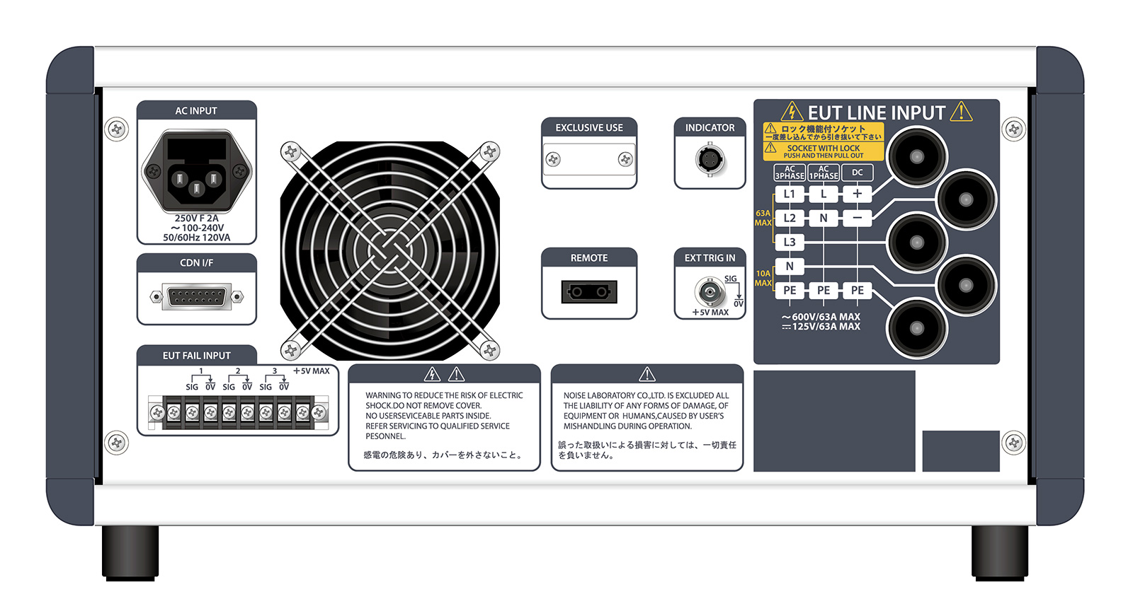
| External interface | REMOTE (For external PC control), CDN I/F (For external CDN), INDICATOR (For Warning Lamp or indicator lamp) EUT FAIL INPUT (For temporary pause at EUT failure event) |
| Accessories | Power Cable, SG Cable, Line Input Cable, Output Cable, Waveform Check Connector, Coaxial Cable, Operation Manual, Accessoriesies bag |
| Operating environment | Temperature 15 to 35 °C Relative humidity 25 to 75% |
| External Dimensions / Weight | (W)430 x (H)199 x (D)370 mm (excluding protrusions) / Approximately 14 kg (A20 model) and 22 kg (B63 model) |
| Power supply | AC 100 to 240 V ± 10% 50/60 Hz approx. 120 VA |
Contact
Repair, Inspection and Calibration
Customer Service CenterNew Purchase Consultation, Materials Request
Product Inquiry Form
Options
-

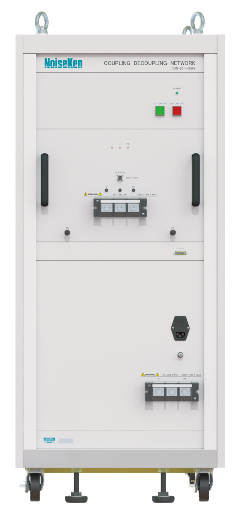
Coupling unit (DC600V / 200A for high power capacity)
This tester can be combined with the Fast transient / burst simulator to do the noise coupling test on 3 wires (+ /-/ PE) up to DC600V / 200A.
In combination with FNS-AX4, it is possible to test by switching the discharged phase or setting the sweep discharged phase.
It is possible to evaluate the burst noise immunity when charging EV / PHV vehicles, which is required with ECE R10-05 / 05. (Supports CHAdeMO)
※When using this coupling unit, it needs to modify the tester. For details, please contact us.
Applicable product: FNS-AX4 series -

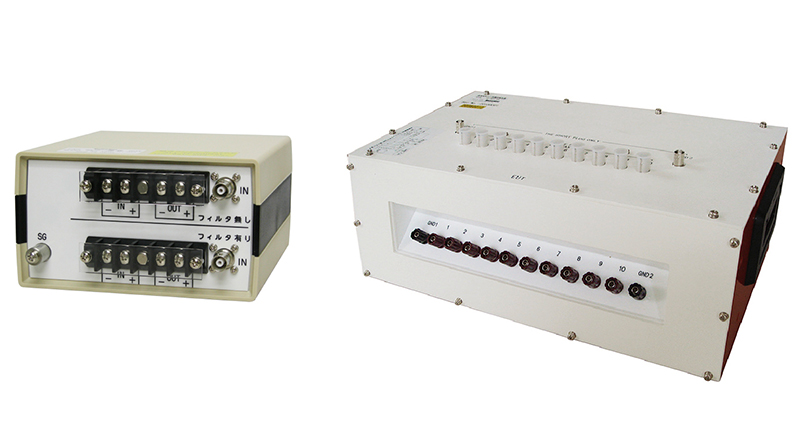
Coupling Fixture for High Frequency Surge Test
Coupling fixture provided to inject noise to harness in combination with Fast Transient Burst simulator.
The varieties of coupling capacity are lined up. Please contact us for details. -

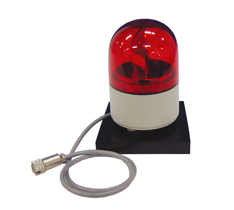
Warning Lamp MODEL : 11-00008B
Alarm lamp for FNS-AX4 series. Alarm lamp illuminated when high voltage is generated at the time of test. -

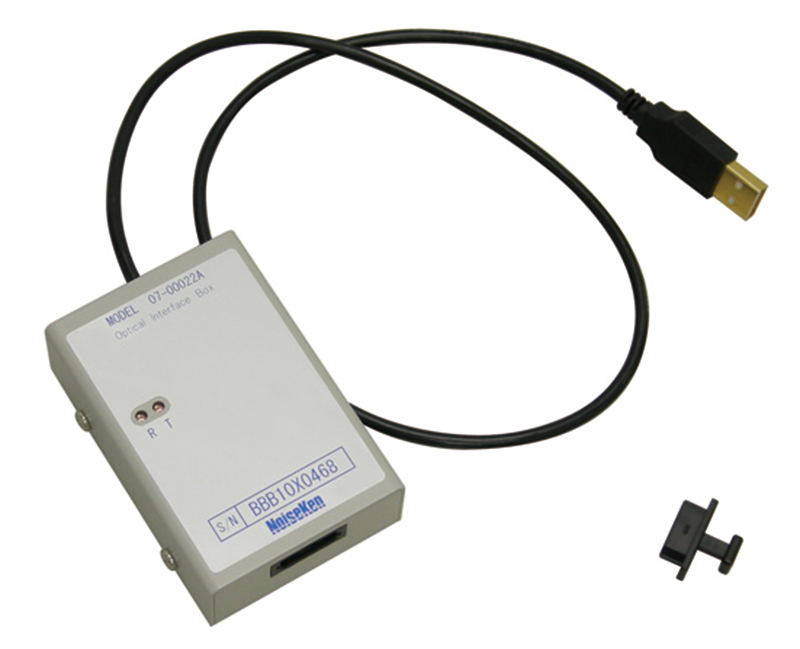
Optical USB module MODEL : 07-00022A
Conversion adapter to interface with PC for the remote control of FNS
USB to optical interface. Fiber cable 5m included. -

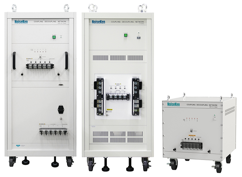
High power Coupling Decoupling Network
High power Coupling Decoupling Network (CDN) can be provided for customers’ requirements.
Please consult with us for details. -

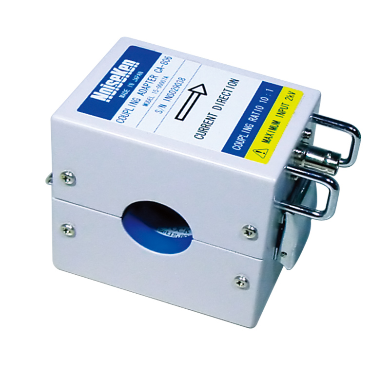
Coupling Adaptor MODEL:15-00007A (CA-806)
15-00007A (CA-806) makes testing for noise tolerance possible by just clamping interconnection cable of electrical equipment in combination with FNS series. -

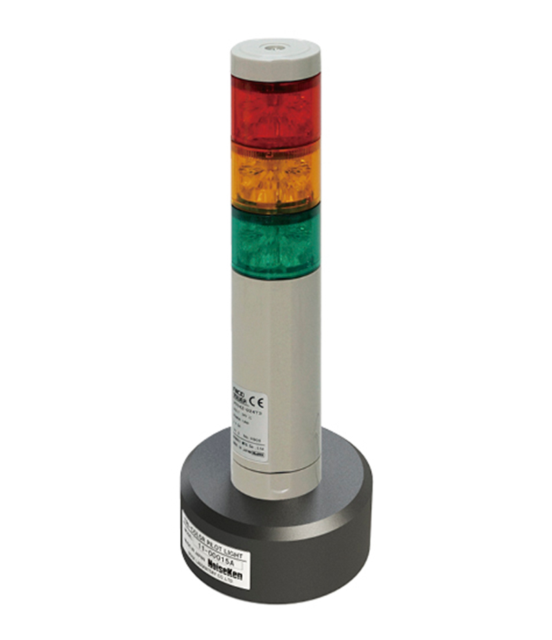
Tri-color pilot light MODEL:11-00015A
The light is for FNS-AX4 series. Three colors indicate corresponding simulator's test status change. -

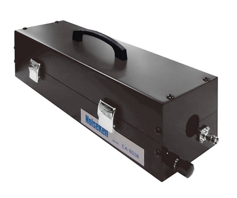
Coupling Adaptor MODEL:CA-805B
CA-805B makes testing for noise tolerance possible by just clamping interconnection cable of electrical equipment in combination with FNS series. -

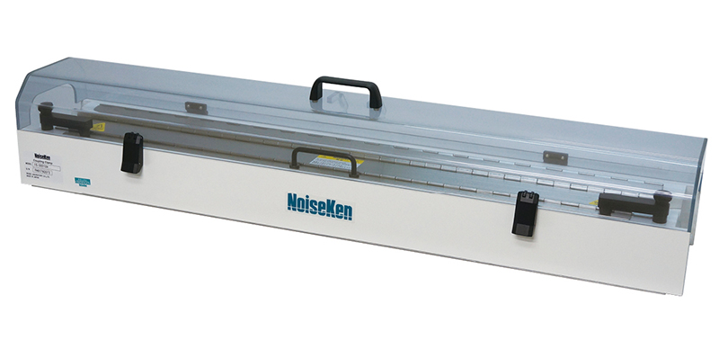
Coupling Clamp MODEL:15-00018A
Coupling clamp for capacitive coupling test on interconnection lines complying to IEC61000-4-4 Ed.3. In addition, calibration fixture for coupling clamp is available. -

Coupling Clamp MODEL:15-00012A
Coupling clamp for capacitive coupling test on interconnection lines complying to IEC61000-4-4 Ed.3. In addition, calibration fixture for coupling clamp is available. -

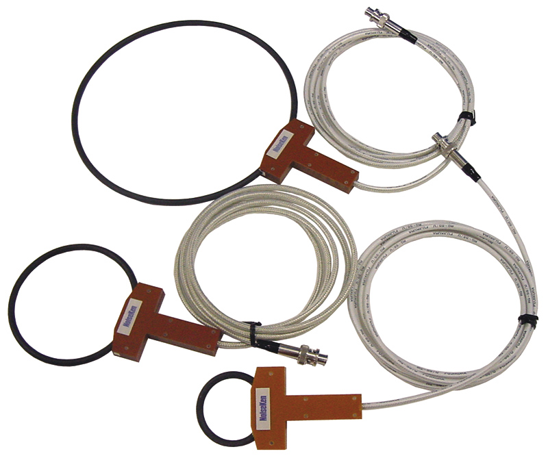
Radiation Probes MODELS:01-00006A/7A/8A/9A/10A/31A/50A
Probes for irradiation of noise at wiring on PCB of electronic equipment. Weak noise tolerance points can be detected using the probe. -

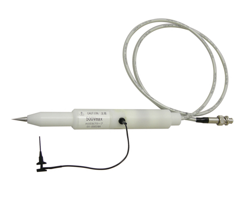
Noise Injection Probe MODEL: 01-00034A
○Direct noise injection on a LSI pin makes the board level noise tolerance testing possible.
○Maximum injection voltage up to 500 V.
○Optional coupling capacitor available (Option) -

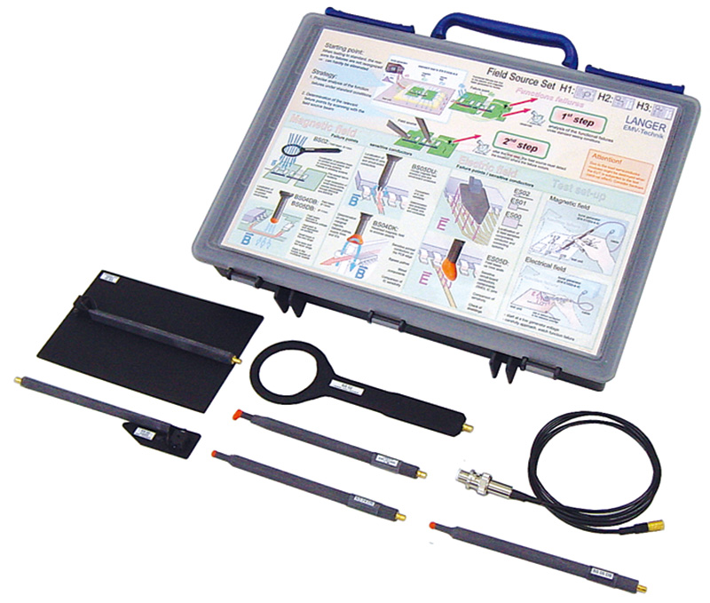
EMS Probes Kit MODEL : H2-B
Probes kit to enable the noise injection onto PCB patterns, flat cables, etc. The probes can be selected to use for either electric fields or magnetic fields in order to irradiate in the near field. -

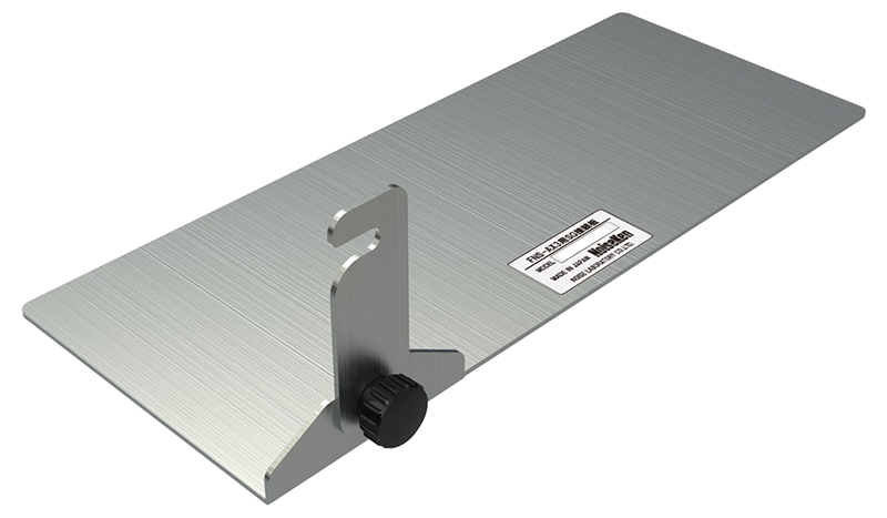
SG terminal connection plate
A metal plate that connects the tester body SG and the ground plane.
Since it doesn't need to screw it to the ground plane, it is easy to move the tester. -

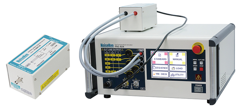
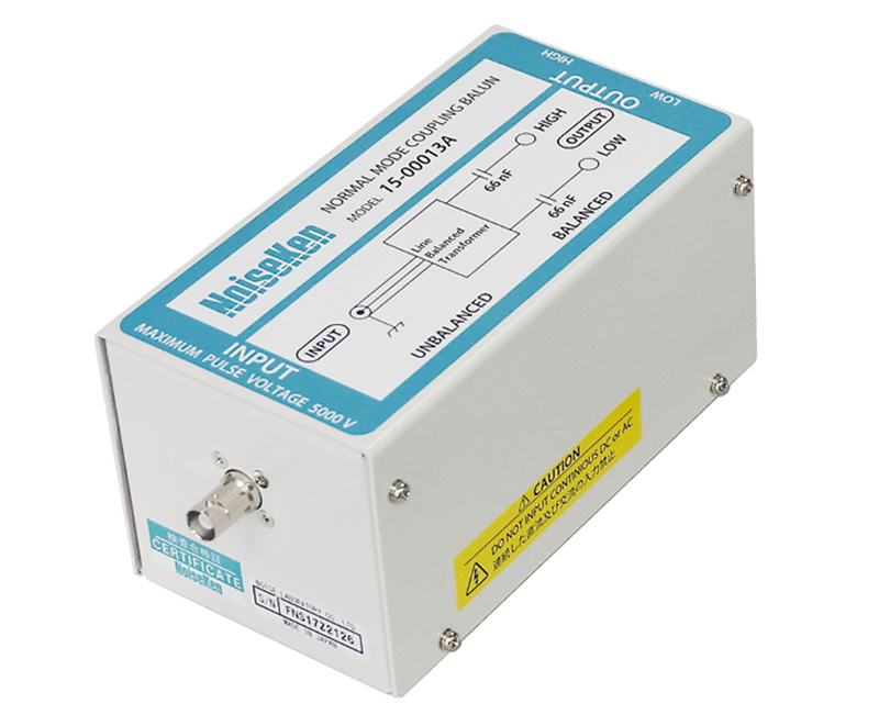
Normal mode coupling balun MODEL:15-00013A
The product allows injection of test voltage on EUT with Normal mode.
5 kV Max. -

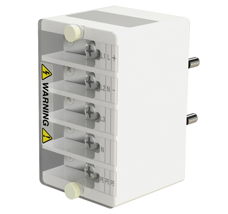
OUTLET BOX (terminal block type)
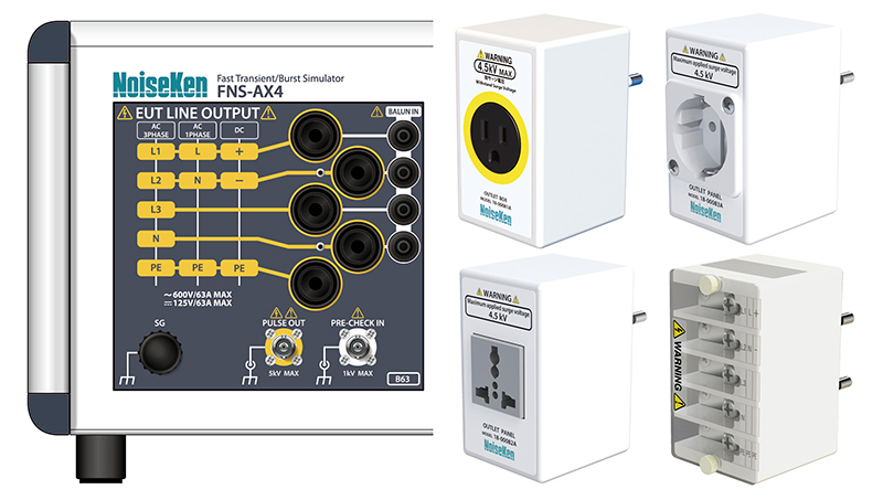
OUTLET BOX converts LINE output socket. -

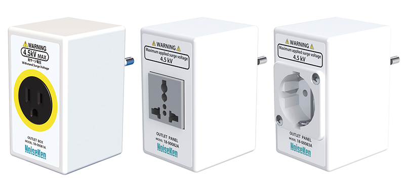
OUTLET BOX MODEL:18-00081A/82A/83A
OUTLET BOX converts LINE output socket.
-

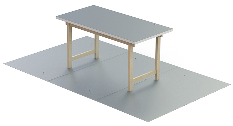
Insulating support MODEL : 03-00024A
Keep the EUT and its wirings 10cm afloat above the ground plane
Size: W1200 x D1200 x H100 mm
Material: Wood
Withstanding load: 500 kg -

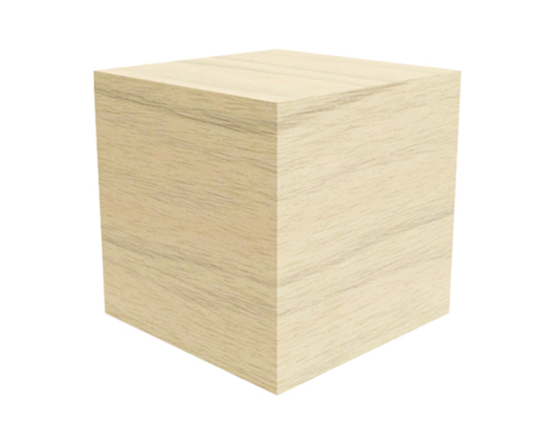
Cubic insulator block MODEL : 03-00029A
Keep the EUT and its wirings 10cm afloat above the ground plane
Size: W100 x D100 x H100 mm
Material: Wood
4 pcs per set -

Test Environment MODEL : 03-00020A/39A/7A
-

Insulating block MODEL : 03-00054A
Keep the EUT and its wirings afloat above the ground plane
Size: W300 x D300 x H50 mm
Material: foamed polyethylene
5 pcs per set -

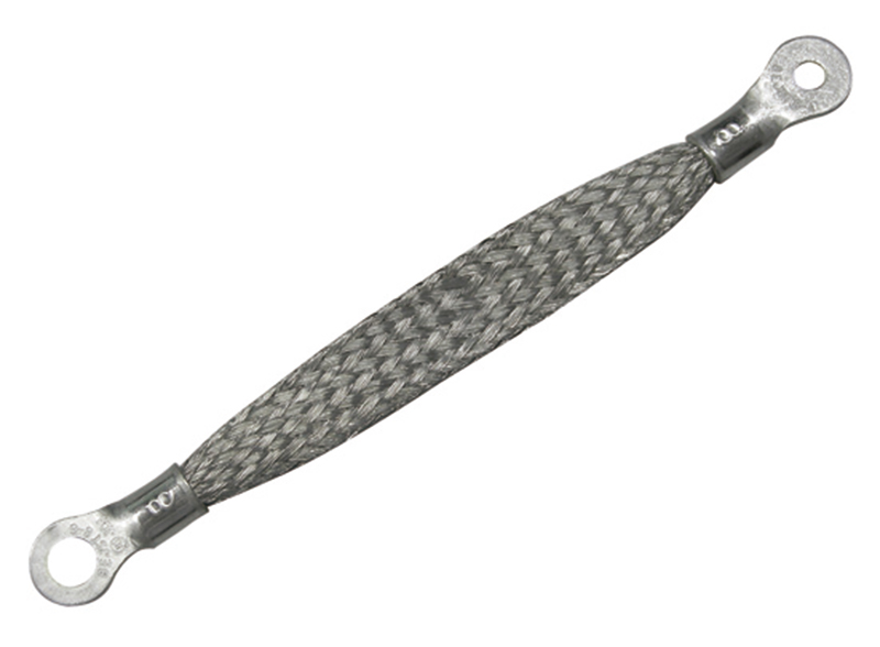
SG cable MODEL : 05-00103A
Braided wire cable to connect between SG terminal of the main unit and the ground reference plane.
Length: 0.1 m
-

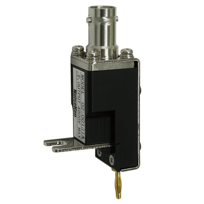
Connector for Waveform Observation of CDN MODEL : 02-00131A
●This is used to measure the output waveform in the CDN part.
●Target model: FNS-AX3 series -

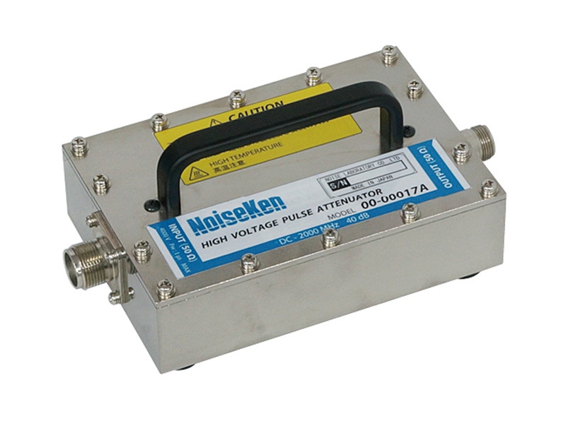
Attenuator for waveform check MODEL : 00-00017A
Attenuator for measuring high voltage pulse. -

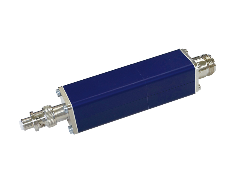
Attenuator for waveform check MODEL : 00-00018A
Attenuator for measuring high voltage pulse.


